|
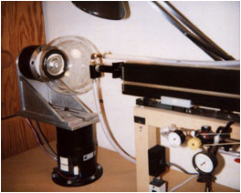
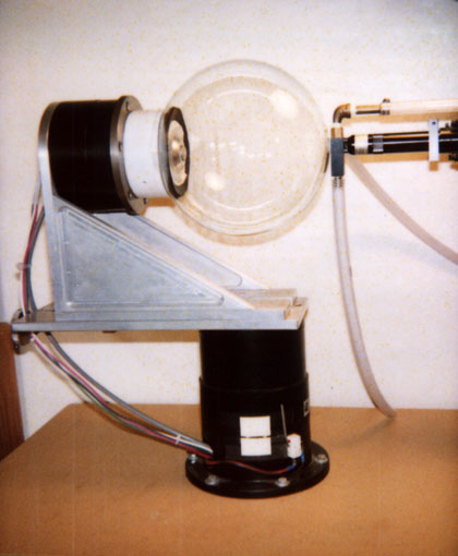
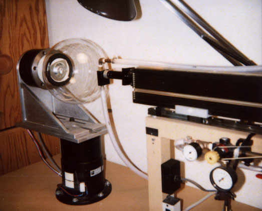
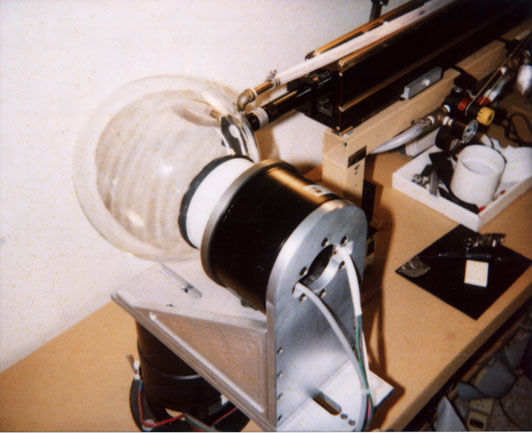
The jig to support the upper servo motor and to attach the globe to that motor were designed by myself and fabricated by a local machinist. The laser itself is mounted on a linear slide that is bolted to the laser support structure. The laser slides easily away from the globe during setup and lens changes and is kept up against the globe by the simple expedient of a rubber band. To insure that the focal point of the laser lens is right at the surface of the globe the laser rides against the globe with a Delran washer acting as the stop. During early testing it was found that silicon oxides were being ejected back onto the laser lens. This was a problem as the power of the beam was being reduced. An air curtain was established using an air jet at right angles to the beam. Tubing is shown carrying air to the air jet and carrying air away. The engraving is composed of dots about .006" in diameter. The laser beam actually melts a small portion of the surface of the glass leaving a dot on the surface. Placing dots adjacent to each other produces the appearance of a line. The information that is placed on the globe includes: an origin cross hair marking the location for which the dial is made, a north or south pole, the equator and tropic of Cancer and Capricorn lines, an horizon line, analemmas at each hour, numbers labeling the hours(and daylight saving time hours if used), the outline of the continents and islands of area greater than 50 square km. and of lakes of area greater than 650 square km., the latitude and longitude for which the dial was made and a label and serial number. In total about 140,000 dots are placed on the globe. Two commands are sent to the server controller for each dot , one in the form of a relative polar distance and a relative right ascension and one command to fire the laser. The laser is not fired until the globe has been moved into position by the upper servomotor controlling right ascension and the lower servomotor controlling polar distance. Depending upon the distance moved servo gains are set and the approach to position is monitored by the servo controller. As the desired position is nearly achieved, the servo gains are increased until the desired position is established. Once the position move has been made the laser is fired. The parameters to be varied here are the power setting of the laser, a 25 watt CO2 laser, and the duration of the pulse. It turns out that the best results are achieved by not one plus but a series of many short pulses. To get this capability I relearned the circuit theory that I had forgotten some years prior. The position command for each dot is computed on a separate computer, a Macintosh. The software environment used is Runtime Revolution, a beautiful general purpose programming environment. The resolution of the servomotors is such that a dot may be placed on the globe to within 0.000709 degrees or 0.04254 minutes or 2.5524 seconds of arc. Since the globe is attached directly to the armature of the servomotor, there is no backlash or hysteresis to worry about. The database for the outline of the continents was developed by the CIA and is in the public domain. The database is given as a series of latitude and longitude values. These values are converted to relative values for placement on the globe. The various other items that are put on the globe are computed for each globe being made. Dots are placed on the globe at a rate of about two per second. This means that the total engraving time is about 20 hours, usually spread out over a four day period. |